PCB Assembly
PCB Bill of Materials
The following components are required to assemble the PCB:| Item Name | Part Number | Quantity |
| Lantern Soldering Jig | LPMSJ1 | 1 |
| Lantern PCB | LPMPCB1 | 1 |
| 3.5mm Headphone Jack | PJ-3583-B | 16 |
| 10KΩ Resistor | C385441 | 2 |
| 68KΩ Resistor | C385541 | 1 |
| 33KΩ Resistor | C385498 | 1 |
| 12KΩ Resistor | C385449 | 1 |
| 180KΩ Resistor | C385460 | 1 |
| 10uF 25V 4*5 Capacitor | C43846 | 1 |
| 22uF 25V 4*7 Capacitor | C43840 | 1 |
| MCP3008 | MCP3008-I-P | 2 |
| 40-pin GPIO header | C169819 | 1 |
The boards sold by Lantern are RoHS compliant and require lead free solder. If you print the boards yourself, just make sure your solder matches your boards.
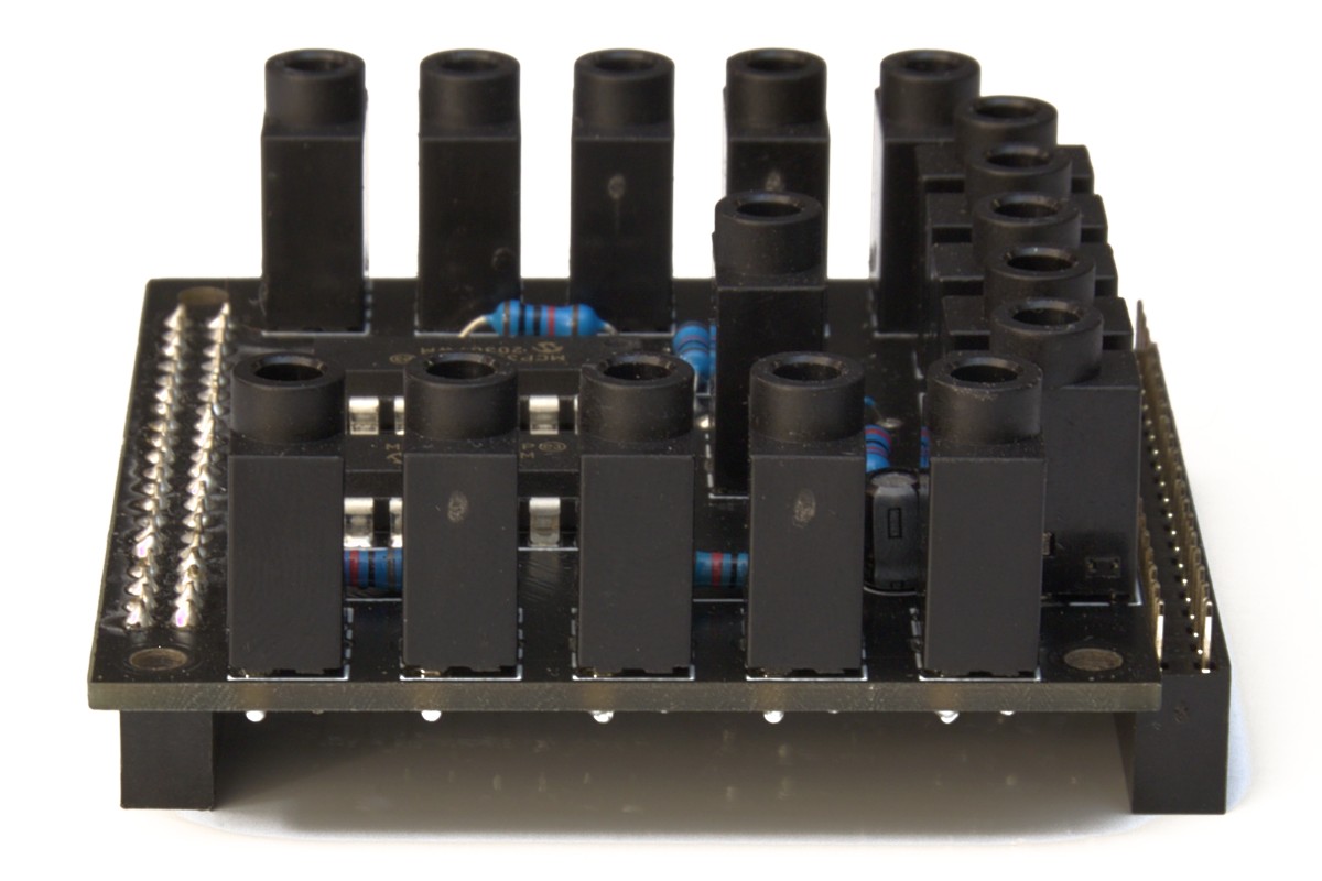
1. Headphone Jacks
Aligning all 16 headphone jacks is incredibly difficult. It's recommended that you acquire or print a Lantern Soldering Jig to help with aligning the headphone jacks. If you choose to do it without one, balance the board on headphone jacks at the corners first, get them soldered, and then move on to the others.
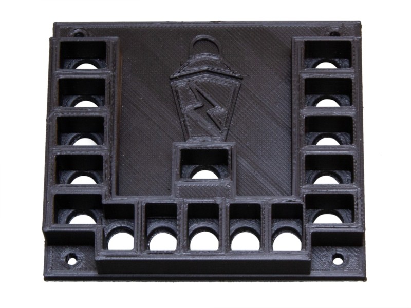
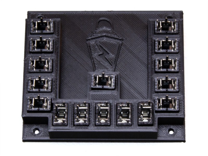
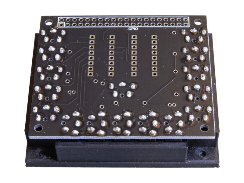
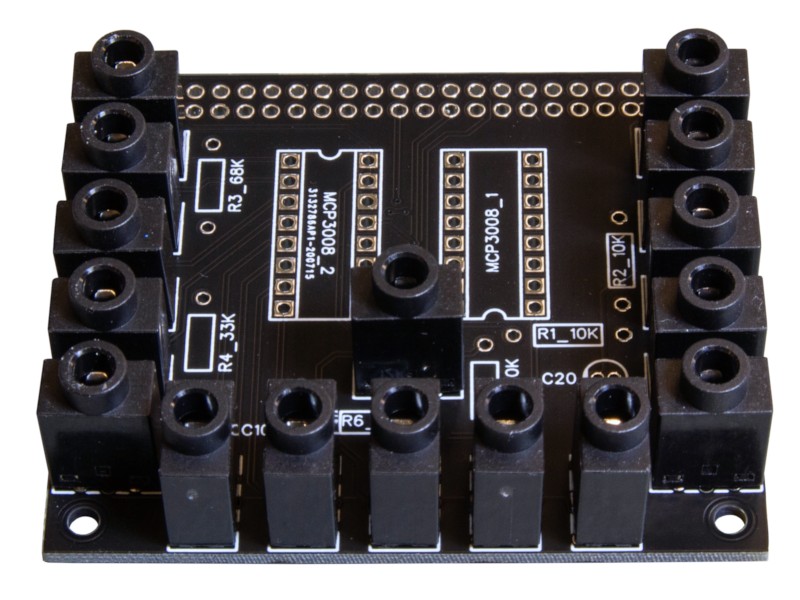
The labeled side of the PCB goes face down on the jig. Make sure the pins on the headphone jacks match orientation in the photo above. When placing the PCB on the headphone jacks, you might have to jiggle it some to get it to drop on the pins. If it doesn't go on easily, check for any bent pins on the headphone jacks.
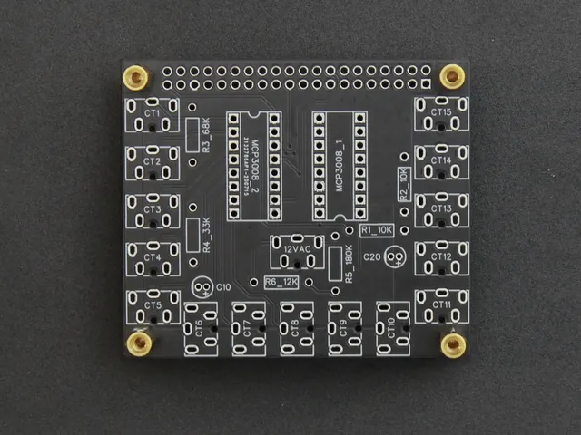
2. Resistors
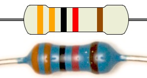
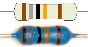
All 6 resistors are clearly labeled on the PCB, so soldering these on should be fairly straightforward. Use the color banding guide below to make sure you have the right resistor for each spot.
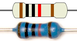
10kΩ
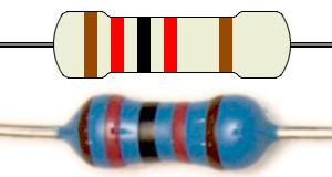
12kΩ
33kΩ
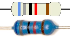
68kΩ
180kΩ
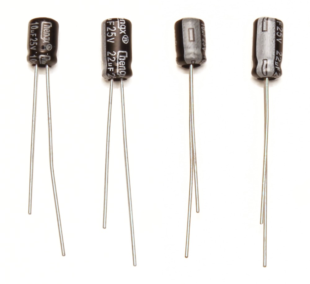
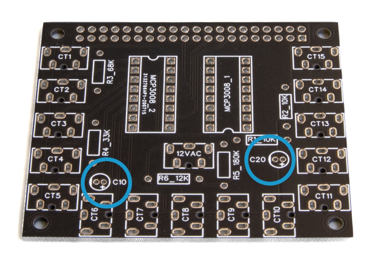
3. Capacitors
There are two capacitors, one 10µF and one 22µF. The 10µF goes in C10 and the 22µF goes in C20 (on V1 boards) or C22 (on all new boards). The board has a + sign on the hole for the positive terminal of the capacitor. The longer of the two terminals on the capacitor is positive, the short side has a white stripe with a negative symbol on it. Make sure the positive terminal goes through the positive hole.
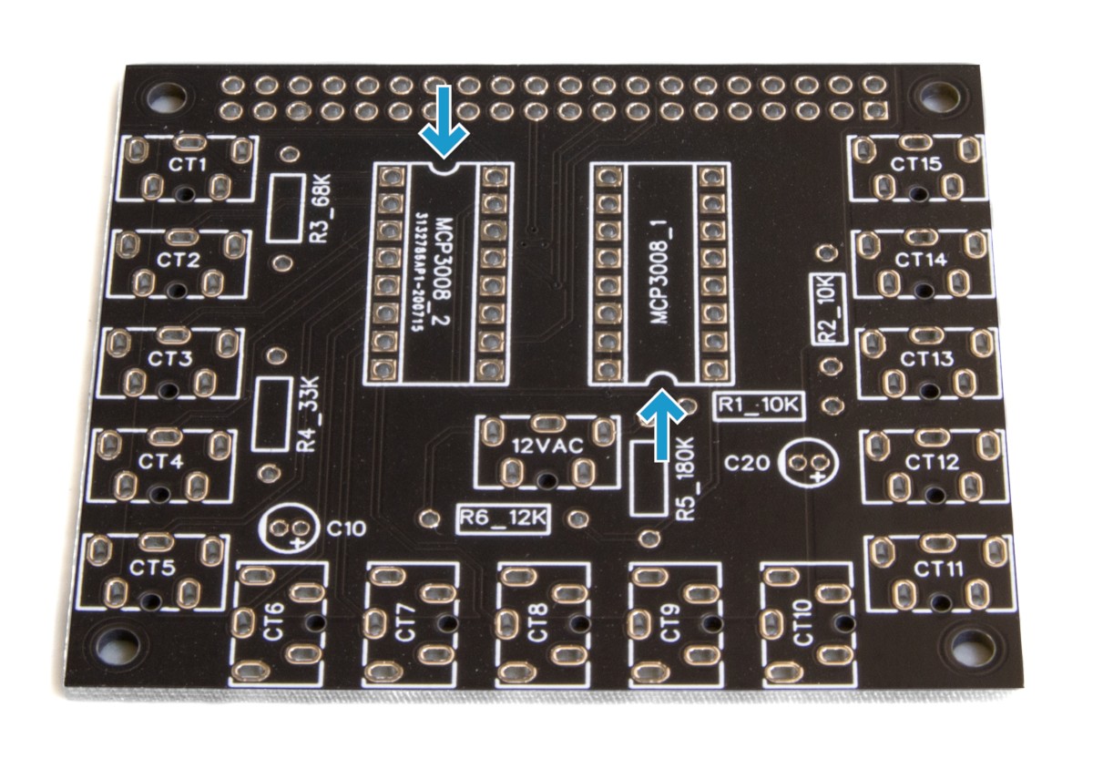
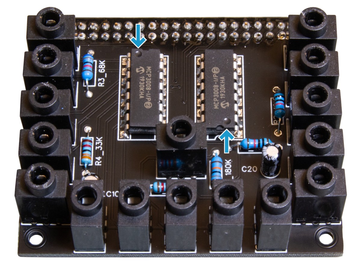
4. Analog to Digital Converters
The ADCs must be soldered in the proper orientation. There is a small indentation on the diagram on the board and a small dot on the chip that must align. The pins need to be compressed a little bit to get it to go into the board.
5. 40 Pin Header
To get the board to sit on the header properly, one side of it needs to be propped up so it sits level while you solder.